The Craftsman 1/2 HP garage door opener is one of the most widely used models in American homes, thanks to its durability, performance, and affordability. Whether you’re installing a new unit, replacing a wall control, or fixing a faulty connection, understanding the wiring diagram for Craftsman 1/2 HP garage door opener is crucial.
Correct wiring is essential not only for the opener to function properly but also for the safety of your home and garage. A wiring mistake can cause the opener to malfunction, trip circuit breakers, or even pose a fire risk. That’s why it’s important to follow an accurate and detailed wiring layout.
Read too: How to Perform a Chamberlain Garage Door Opener Code Change? Mastering Security
In this comprehensive guide, we’ll walk you through everything you need to know about the wiring diagram for Craftsman 1/2 HP garage door opener, including the essential components, wiring color codes, sensor placement, wall console connections, and troubleshooting tips. Whether you’re a DIY homeowner or a technician-in-training, this guide is designed to make the wiring process clear and straightforward.
Understanding the Basics: Craftsman Garage Door Opener Wiring
Before diving into the actual diagram, it’s important to understand the key components involved in wiring a Craftsman 1/2 HP garage door opener.
Key Components Include:
- Opener Motor Unit: The main power unit mounted on the ceiling
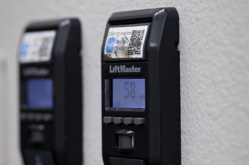
- Wall Control Panel (Wall Console): A low-voltage device to open/close the door
- Safety Sensors (Photo Eyes): Located near the bottom of the tracks to prevent closure if something blocks the door
- Power Cord: Connects the motor unit to the home’s electrical supply
- Limit Switches: Used to set how far the door opens and closes
- Remote Receivers: Built into the motor for wireless remotes
- Light Socket Wiring: Usually connected to the motor housing
All of these parts work in unison to open, close, and secure your garage door. The wiring diagram shows how these components are connected electrically.
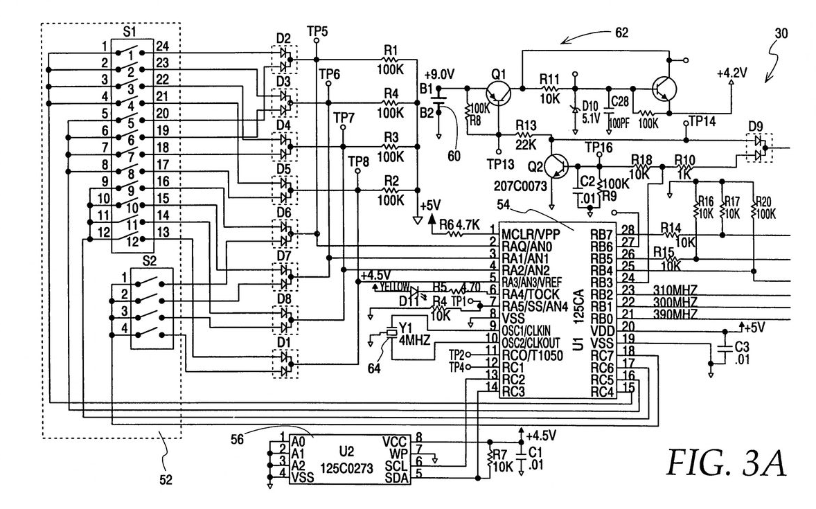
Wiring Diagram for Craftsman 1/2 HP Garage Door Opener – Explained Step by Step
The wiring diagram for Craftsman 1/2 HP garage door opener typically comes with the unit’s user manual or is found on the inside of the opener’s access panel. However, if yours is missing, faded, or confusing, this section breaks it down.
1. Power Supply Wiring (120V AC)
The opener motor unit requires a standard 120V AC power source.
- Black Wire (Hot) — Connects to the black wire from the ceiling outlet or power cord
- White Wire (Neutral) — Connects to the white wire from the outlet
- Green/Bare Wire (Ground) — Should be attached to a grounding screw or terminal
Important: Always turn off the circuit breaker before handling power wires.
2. Wall Control Panel Wiring (Low Voltage)
The wall console is typically powered by a low-voltage circuit (24V DC) that connects directly to the opener’s terminal block.
- Terminal 1 (White): Connects to white wire from wall control
- Terminal 2 (Black/Red): Connects to red wire from wall control
Tips:
- Use 18- or 22-gauge bell wire
- Keep wires away from sharp metal edges
- You can use existing wiring from a previous opener if intact
3. Safety Sensor Wiring (Photo Eyes)
The safety reversing sensors are located on each side of the garage door, about 4 to 6 inches above the floor. Each sensor connects to the opener with two wires.
- Sensor #1 (Left Side): One white wire and one black/white wire
- Sensor #2 (Right Side): Same color wires as above
Connect these wires to:
- Terminal 2 (Black/White wires) — From both sensors
- Terminal 3 (White wires) — From both sensors
Sensors are polarized, so wiring them backwards may cause blinking or malfunction. Ensure the wires match at both ends.
4. Garage Door Limit Switch Wiring
Limit switches control how far your door travels during opening and closing. Most modern openers have adjustable knobs or dials rather than manual wiring for limit switches. However, if yours is older, it may have physical limit switches that include:
- Blue Wire: Close limit
- Orange Wire: Open limit
- Common Wire (Black or White): Shared with both limit switches
Refer to your unit’s model for specifics.
5. Light Socket Wiring
The motor unit often includes a socket for a garage light bulb. This turns on when the opener is activated or when motion is detected (if equipped). This internal wiring is usually pre-installed and doesn’t require user modification.
- Black wire: Hot
- White wire: Neutral
- Internal relay: Controls on/off timing (usually automatic)
Common Color Codes for Craftsman Garage Door Wiring
| Wire Color | Purpose | Notes |
|---|---|---|
| White | Neutral or low-voltage common | Often used for both wall panel & sensors |
| Black | Hot (AC power) or signal | Can be power or control wire |
| Red | Wall button signal | Low voltage |
| Green | Ground | Always connect to grounding screw |
| Black/White | Sensor signal | Polarized with white wire |
Note: Always double-check wire colors against your opener’s model-specific instructions.
Wiring Tools You’ll Need
To wire or rewire your Craftsman 1/2 HP opener properly, you’ll need:
- Flathead and Phillips screwdrivers
- Wire strippers
- Electrical tape
- Voltage tester or multimeter
- Wire nuts or quick-connect terminals
- Ladder
- Flashlight (for tight spots)
Safety Tips Before You Start Wiring
- Turn off power at the breaker box before working
- Never mix low-voltage and high-voltage wires
- Ensure all connections are secure to avoid electrical shorts
- Use insulated tools to avoid shock
- If you’re unsure, consult a licensed electrician
Troubleshooting Common Wiring Issues in Craftsman 1/2 HP Openers
1. Wall Control Not Working
- Check if wires are reversed
- Inspect terminals on both ends for corrosion
- Ensure proper contact at the opener unit
2. Safety Sensors Blinking
- Wiring might be reversed
- Clean lenses
- Check for physical alignment
- Ensure consistent power to both sensors
3. Opener Has Power But Doesn’t Operate
- Double-check 120V connections
- Inspect fuse or circuit board
- Make sure wall button and sensors are properly connected
4. Remote Works But Wall Button Doesn’t
- Wall button wire may be broken
- Replace wall control panel
- Test terminals with a multimeter for voltage
Upgrading Old Craftsman Opener Wiring
If your opener is more than 15 years old, consider upgrading:
- Replace all wires with new low-voltage rated wire
- Switch to smart wall consoles compatible with newer remotes
- Upgrade safety sensors for improved reliability
- Install a surge protector to protect internal circuitry
Wiring upgrades improve performance and safety, especially for older models that may no longer meet updated electrical codes.
Wiring Diagram for Craftsman 1/2 HP Garage Door Opener — Visual Reference and Placement
Below is a simplified visual reference of how the components typically connect. (Since this is text-only, imagine the diagram as a list layout)
scssCopyEdit[Wall Console] ----(2-wire low voltage)----> [Terminal 1 & 2 on Motor Unit]
[Left Sensor]  ----(white & black/white)----> [Terminal 2 & 3 on Motor Unit]
[Right Sensor] ----(white & black/white)----> [Terminal 2 & 3 on Motor Unit]
[Motor Unit]  ----(AC Wiring)----> [House Power Supply]
[Light Bulb Socket] ----(internal wiring)----> [Relay Controlled by Motor Board]
Always follow manufacturer-specific diagrams when available, but this layout serves as a general guide for Craftsman openers.
Conclusion
Understanding the wiring diagram for Craftsman 1/2 HP garage door opener is essential for safe and effective installation, repair, or troubleshooting. Whether you’re setting up the opener for the first time or diagnosing why your wall control or safety sensors aren’t working, following the correct wiring procedure ensures that your system operates smoothly and safely.
From the power supply to the sensors and wall control, each wire has a purpose and should be handled with care. With the help of this guide, you can confidently manage your garage door opener’s wiring and make informed decisions about maintenance, upgrades, or repairs.
If you ever feel uncertain about the process, don’t hesitate to consult a qualified electrician or garage door technician—your safety comes first.
Leave a Reply