If you’re a homeowner or DIY enthusiast working on your garage, having access to a Craftsman 1 2 Hp Garage Door Opener wiring diagram can save time, reduce installation errors, and help you safely troubleshoot electrical issues. Whether you’re wiring the opener for the first time, replacing an old wall control, or integrating safety sensors, a detailed diagram is a must-have tool.
This in-depth guide explains every component and wiring step you need to know to properly set up or repair a Craftsman 1/2 HP garage door opener. You’ll also find troubleshooting tips, safety considerations, and answers to frequently asked questions.Why Wiring Diagrams Are Essential for Garage Door Openers.
Read too: How To Replace Garage Door Roller Like a Pro? Step-by-Step Guide
Understanding the electrical layout of your Craftsman 1/2 HP garage door opener is critical for:
- Installing new parts (wall controls, safety sensors, lights)
- Repairing faulty connections
- Upgrading old wiring or control boards
- Complying with safety codes
- Preventing electrical shorts or fire hazards
Wiring diagrams show how each component is connected to the motor unit, power source, and accessories like remotes and keypads.
Main Components in a Craftsman Garage Door Opener Wiring System
Before diving into the actual Craftsman 1 2 Hp Garage Door Opener wiring diagram, it’s important to understand the key components that are wired into the system:
1. Motor Head Unit
Located on the ceiling, this is the main body of the opener that contains the motor, control board, and terminal screws.
2. Wall Control Panel
Also called the door control button, this is the switch mounted inside the garage near the door.
3. Safety Sensors (Photo Eyes)
Installed on each side of the garage door track, they detect obstacles to prevent the door from closing on people, pets, or objects.
4. Power Supply (AC Power)
Most Craftsman 1/2 HP models plug directly into a standard 120V AC outlet.
5. Wiring Terminals
Usually color-coded terminals (red, white, black) located on the opener head for connecting wires from sensors and the control panel.
Craftsman 1 2 Hp Garage Door Opener Wiring Diagram Explained
Here’s a step-by-step overview of the Craftsman 1 2 Hp Garage Door Opener wiring diagram, simplified for clarity.
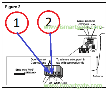
A. Terminal Layout (On the Opener Head Unit)
Most Craftsman openers have three screw terminals:
- RED Terminal (1) – Connects to the wall control (often white wire with red stripe)
- WHITE Terminal (2) – Shared ground for both the wall control and safety sensors
- BLACK Terminal (3) – Connects to safety sensor receiving unit (often solid white or black wire)
🔧 Tip: The actual terminal colors may vary slightly depending on the model year, but these functions are fairly standard for 1/2 HP Craftsman openers.
B. Wiring the Wall Control Panel
Tools Needed:
- Screwdriver
- 18-22 gauge low-voltage wire
- Wire strippers
Steps:
- Connect the white/red-striped wire from the wall control panel to the RED terminal on the opener head.
- Connect the solid white wire to the WHITE terminal.
- Secure the wires neatly along the wall using staples or clips.
- Mount the wall control panel near the garage door.
🧠 Note: Reversing the wall control wires won’t typically damage the unit but can prevent it from working properly.
C. Wiring the Safety Sensors (Photo Eyes)
Safety sensors are required by law for all garage door openers manufactured after 1993. They must be correctly aligned and wired to function.
Steps:
- Mount the sensors 4-6 inches off the ground on both sides of the garage door track.
- Run two wires from each sensor to the opener.
- Sender Sensor (orange/black wires):
- Orange wire connects to the BLACK terminal.
- Black wire connects to the WHITE terminal.
- Receiver Sensor (white/black wires):
- White wire connects to the WHITE terminal.
- Black wire connects to the BLACK terminal.
💡 Tip: Some newer sensors use color-coded plugs instead of raw wires. Always refer to the color guide and make sure the LED lights on both sensors are solid (not blinking).
Troubleshooting Wiring Issues
Wiring a Craftsman 1 2 Hp Garage Door Opener isn’t difficult, but a single loose wire or incorrect connection can prevent the system from functioning.
Common Symptoms of Wiring Problems:
| Symptom | Likely Cause |
|---|---|
| Door doesn’t respond to wall button | Loose wall control wire or incorrect terminal |
| Door reverses immediately | Safety sensors misaligned or miswired |
| LED on wall button is off | Dead wire or reversed polarity |
| No power to opener | Tripped breaker or blown fuse |
How to Test the Wires:
Use a multimeter to test continuity across each wire:
- Disconnect the wires from the terminal screws.
- Touch the multimeter leads to both ends of the wire.
- If there’s no beep or reading, the wire is damaged.
Replace or re-route new wire as needed using 18/2 thermostat wire or garage opener low-voltage wire.
Upgrading to Wireless Controls or Smart Systems
Many homeowners choose to upgrade from basic wall buttons and remotes to more advanced control systems. Some popular upgrades include:
1. Wireless Keypads
- Allow secure access via 4-digit code
- Mount outside the garage door
- Wired to the same RED and WHITE terminals or wirelessly synced
2. Smartphone Controllers
- Wi-Fi enabled smart hubs like MyQ (Craftsman-compatible)
- No rewiring needed; plugs into power and connects to the motor unit
Ensure any upgrade is compatible with your Craftsman 1/2 HP model before installation.
Important Safety Considerations
When dealing with opener wiring:
- Always disconnect power at the outlet or breaker before touching wires.
- Avoid using high-voltage wires for low-voltage tasks.
- Use UL-rated wires and indoor-rated insulation.
- Secure wires away from moving parts such as chains and belts.
- Label your wires before disconnecting anything for easier reinstallation.
Improper wiring can lead to fire hazards or injury. When in doubt, contact a licensed electrician or garage door technician.
FAQs About Craftsman Garage Door Opener Wiring
Q1: What wire gauge should I use?
Use 18 or 22-gauge solid copper wire, commonly available at hardware stores labeled as “garage door opener wire” or “thermostat wire.”
Q2: Can I use existing wall wiring from an old opener?
Yes, as long as the insulation is intact and the wires are not corroded or cut. Always test continuity before reusing.
Q3: My remote works but the wall control doesn’t—why?
The issue is likely due to a faulty wire or misconnection at the RED and WHITE terminals. Recheck your wiring and replace the wall button if necessary.
Q4: What if both the wall button and remotes don’t work?
Check the power source and look for blinking lights on the opener. If the motor’s logic board is fried, professional repair or replacement may be needed.
Conclusion
Having access to a reliable and detailed Craftsman 1 2 Hp Garage Door Opener wiring diagram is crucial whether you’re installing a new system, replacing components, or troubleshooting issues. By understanding each wire’s purpose and ensuring all connections are secure and properly routed, you can confidently manage your garage door opener’s wiring system.
From the wall control to the safety sensors, every wire has a critical role. Taking time to follow a proper wiring diagram will not only save you time and money—it also ensures safety and long-term reliability.
Whether you’re an experienced DIYer or a beginner learning the basics, this guide gives you everything you need to wire your Craftsman 1/2 HP garage door opener like a pro.
Leave a Reply