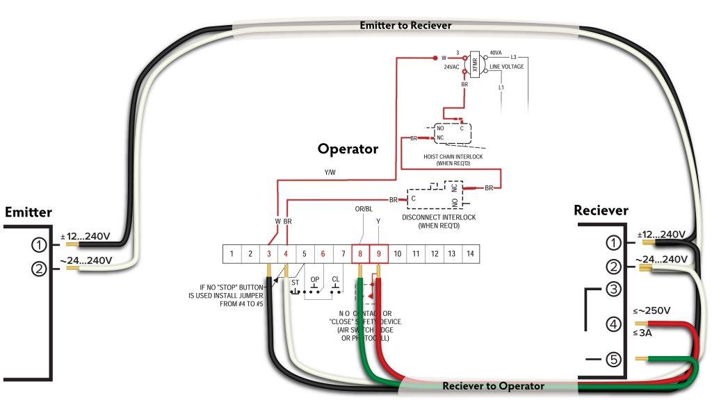
A garage door opener is a convenient and essential component of modern-day garage systems. It automates the process of opening and closing the garage door, providing ease of access and enhanced security. Behind the seamless operation of a garage door opener lies a network of electrical connections that power the system. Understanding the garage door opener wiring diagram is crucial for troubleshooting issues, performing maintenance, or installing a new opener. In this article, we will delve into the details of a garage door opener wiring diagram, explaining the key electrical connections and their functions.
Components of a Garage Door Opener Wiring Diagram
Power Source
The power source is the starting point of the garage door opener wiring diagram. Typically, the opener is connected to a 120-volt electrical outlet. This power supply is essential for energizing the system and ensuring its proper functioning. The power cord from the opener connects to the outlet to draw electricity.
Circuit Board
The circuit board, also known as the logic board or control board, is the brain of the garage door opener. It is responsible for interpreting signals from the remote control, wall-mounted button, or smartphone app and translating them into actions to open or close the garage door. The circuit board contains various components, including relays, capacitors, and resistors, that facilitate the communication and control of the opener.
Safety Sensors
Modern garage door openers are equipped with safety sensors as a crucial safety feature. These sensors are typically mounted near the bottom of the garage door, on each side of the opening. The safety sensors emit an infrared beam that detects any obstruction in the path of the closing door. If an object, person, or pet interrupts the beam while the door is closing, the sensors send a signal to the circuit board, prompting the door to reverse and open again.
Understanding the Wiring Connections
Wall Button Wiring
The wall-mounted control button, located inside the garage, provides a convenient way to operate the garage door. A pair of wires connects the wall button to the opener’s circuit board. Pressing the button completes the circuit, sending a signal to the opener to open or close the door.
Remote Control Wiring
Garage door openers often come with handheld remote controls that allow you to operate the door from a distance. The remote control communicates with the opener through radio signals. The opener’s circuit board receives the signals from the remote control, initiating the door’s movement accordingly.
Safety Sensor Wiring
The safety sensors are an integral part of the garage door opener’s safety system. A pair of wires connects each sensor to the opener’s circuit board. The sensors transmit and receive the infrared beam to detect any obstructions and ensure safe operation of the garage door.
Motor Wiring
The garage door opener motor is responsible for the physical opening and closing of the door. Wires connect the motor to the circuit board, which controls its operation based on signals from the wall button, remote control, or safety sensors.
Conclusion
Understanding the garage door opener wiring diagram is essential for anyone involved in troubleshooting, repairing, or installing a garage door opener. The wiring diagram illustrates the electrical connections that power the various components of the opener, such as the circuit board, safety sensors, motor, and control buttons. Familiarizing yourself with the wiring diagram can help you identify and resolve issues that may arise with the opener, ensuring smooth and reliable operation. Whether you’re a homeowner performing DIY maintenance or a professional garage door technician, a clear understanding of the wiring diagram is a valuable asset in maintaining a functional and secure garage door opener system.
Leave a Reply