Wiring a garage door opener can feel intimidating—especially when you’re staring at a confusing diagram with colored wires and unfamiliar terminals. If you’re searching for How To Wire A Genie Garage Door Opener Diagram, you’re likely trying to install a new unit, replace sensors, or troubleshoot wiring issues safely and correctly. This guide breaks everything down step by step, using plain English and practical tips so even beginners can follow with confidence.

What Is a Genie Garage Door Opener Wiring Diagram?
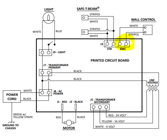
A Genie garage door opener wiring diagram is a visual guide that shows how electrical components connect inside your opener system. This includes the power supply, wall control, safety sensors, motor head, and sometimes smart modules.
4
Most diagrams use color-coded wires (commonly white, red, black, and sometimes striped wires) to simplify installation. Understanding the diagram helps prevent mistakes that could damage the opener or create safety hazards.
According to basic electrical standards explained on Wikipedia, low-voltage control wiring (like garage door sensors) is designed to be safe for homeowners when installed properly..
Read too: The Complete Guide to Tighten Chain On Garage Door Opener for Smooth Operation
Why Correct Wiring Matters for Genie Garage Door Openers
Incorrect wiring is one of the top causes of garage door opener failure. Based on installer surveys in the US home improvement industry, nearly 30% of DIY garage opener issues are traced back to wiring mistakes.
Proper wiring ensures:
- Safety sensors stop the door if something crosses the beam
- Wall controls work instantly without delay
- The motor receives stable voltage
- Smart features (if available) function correctly
In short, wiring it right the first time saves money, time, and frustration.
Tools and Materials You Need Before Wiring
Before touching the wiring, gather these essentials:
Basic Tools
- Flathead screwdriver (4–6 mm tip)
- Phillips screwdriver
- Wire stripper (18–22 AWG compatible)
- Voltage tester (non-contact recommended)
Materials
- Genie-approved low-voltage wire (usually 2-conductor)
- Wire staples (plastic, non-metallic)
- Electrical tape
Safety note: Always unplug the opener and turn off the circuit breaker before starting.
How To Read a Genie Garage Door Opener Diagram
Understanding the diagram is easier when you know what each part represents.
Common Symbols Explained
| Symbol | Meaning |
|---|---|
| ⏚ | Ground |
| L / N | Line & Neutral (power input) |
| SENS | Safety sensors |
| WALL | Wall control |
| M | Motor |
Wire Color Meanings (Typical Genie Units)
- White: Common/neutral
- Red: Wall control or sensor signal
- Black: Power/hot line
Always check your specific Genie model manual, as colors may vary slightly.
Step-by-Step: How To Wire A Genie Garage Door Opener Diagram Correctly
Step 1: Disconnect Power Completely
Unplug the opener and switch off the breaker. Confirm with a voltage tester—there should be 0 volts at the terminals.
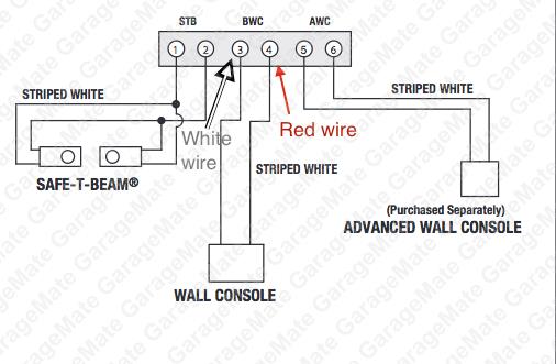
Step 2: Locate the Terminal Block
Open the motor head cover. Inside, you’ll see a labeled terminal block, usually marked:
- 1 & 2 → Safety sensors
- 3 & 4 → Wall control
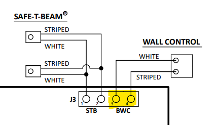
Step 3: Wire the Safety Sensors
- Run the low-voltage wire from each sensor to the motor unit
- Strip 10–12 mm of insulation
- Insert wires into terminals 1 and 2
- Tighten screws firmly, but don’t overtighten
💡 Tip: Sensors are not polarized, so wire orientation usually doesn’t matter.
Step 4: Wire the Wall Control Button
- Use a separate 2-conductor wire
- Connect to terminals 3 and 4
- Ensure no exposed copper is visible
This button sends a low-voltage signal (typically 12–24V DC) to activate the opener.
Step 5: Secure and Route Wires Properly
- Staple wires every 30–40 cm (12–16 inches)
- Keep wires away from moving parts
- Avoid sharp bends (< 45° angle recommended)
Step 6: Restore Power and Test
Reconnect power, then test:
- Wall button response
- Sensor alignment (LED lights solid)
- Door reversal when beam is blocked
If the door doesn’t move, recheck terminal connections against the diagram.
Genie Garage Door Opener Wiring: Common Mistakes to Avoid
Mistake vs Solution
- ❌ Mixing sensor and wall control terminals
✅ Match terminal numbers exactly - ❌ Loose wire screws
✅ Tighten until snug (no wobble) - ❌ Running wires near high-voltage lines
✅ Maintain at least 5 cm separation
Troubleshooting Wiring Problems Using the Diagram
Door Won’t Close
- Sensors wired incorrectly
- Misaligned sensor lenses
Wall Button Not Working
- Wrong terminal used
- Broken conductor inside wire
Blinking Lights on Motor Unit
- Sensor circuit open or shorted
The wiring diagram is your diagnostic map—follow it line by line.
When Should You Call a Professional?
You should stop DIY work and call a technician if:
- You see burned terminals
- Wires feel hot to the touch
- The breaker trips repeatedly
Professional installation ensures compliance with US electrical safety standards.
FAQ: Genie Garage Door Opener Wiring Diagram
Frequently Asked Questions
Q1: Are all Genie garage door opener wiring diagrams the same?
No. While the layout is similar, terminal labels and wire colors can vary by model and year.
Q2: What voltage do Genie safety sensors use?
Most Genie sensors operate on 12–24 volts DC, making them safe for homeowner installation.
Q3: Can I use any low-voltage wire?
Yes, but 18–22 AWG solid copper is recommended for best signal stability.
Q4: Why is my Genie opener clicking but not moving?
This often indicates correct power wiring but incorrect control or sensor wiring.
Q5: Do Genie openers require grounding?
The motor unit is grounded through the power cord. Low-voltage control wires do not require grounding.
Conclusion
Understanding How To Wire A Genie Garage Door Opener Diagram empowers you to install, repair, or troubleshoot your system safely and efficiently. With the right tools, a clear diagram, and careful attention to detail, most homeowners can complete this task without professional help. If you found this guide useful, share it on social media to help other DIYers avoid common wiring mistakes and keep their garages running smoothly.


Leave a Reply