Is Your Garage Door Acting Up?
There is nothing quite as frustrating as pressing the remote button and hearing… silence. Or worse, hearing a strange click but seeing no movement. Before you call an expensive technician or replace the entire unit, you might be dealing with a faulty brain: the logic board. Learning how to test logic board on garage door opener systems can save you hundreds of dollars and hours of waiting. This guide will walk you through the diagnostic process safely and effectively, helping you determine if a simple reset, a minor repair, or a full replacement is needed.
Why the Logic Board is the Heart of Your System
The logic board, often called the main control board or motherboard, is the central processing unit of your garage door opener. It receives signals from your wall console, remote controls, and safety sensors, then instructs the motor to engage or disengage.
When this component fails, the symptoms can be misleading. You might think the motor is dead, the remote is broken, or the sensors are misaligned. However, in many cases, the issue lies within the circuitry of the board itself. According to industry data, electronic component failure accounts for nearly 30% of all garage door opener service calls, making it one of the most common points of failure after wear-and-tear on mechanical parts like springs and rollers.
Understanding how to isolate this component is crucial for any homeowner looking to maintain their property efficiently.
Safety First: Preparing for the Test
Before touching any internal components, safety must be your top priority. Garage door openers operate on high voltage, and even when unplugged, capacitors on the logic board can hold a dangerous electrical charge.
- Disconnect Power: Unplug the opener from the ceiling outlet. If it is hardwired, turn off the circuit breaker dedicated to the garage.
- Discharge Capacitors: Wait at least 5–10 minutes after unplugging to allow residual power to dissipate.
- Use Insulated Tools: Always use screwdrivers and multimeters with insulated handles.
- Secure the Door: Ensure the garage door is closed and locked in place so it does not fall unexpectedly during testing.
Pro Tip: If you are uncomfortable working with electrical components, do not hesitate to call a professional. No DIY savings are worth the risk of electrical shock.
Step-by-Step: How to Test Logic Board on Garage Door Opener
Testing the logic board requires a methodical approach. We will move from the simplest checks to more advanced diagnostics using a multimeter.
Step 1: Visual Inspection for Burn Marks
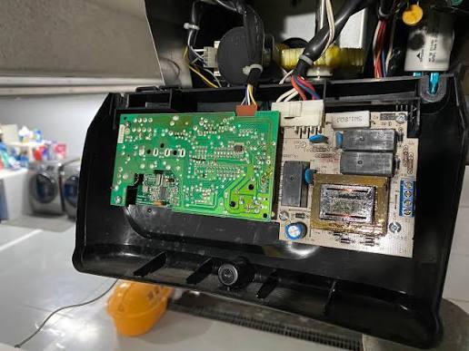
Remove the outer casing of the garage door opener to expose the logic board. Look closely for any signs of physical damage.
- Burnt Components: Look for blackened areas, melted plastic, or charred resistors.
- Bulging Capacitors: Capacitors should be flat on top. If they are domed or leaking fluid, they have failed.
- Loose Connections: Check if any wires are disconnected or if solder joints appear cracked.
If you see visible burn marks, the board is likely damaged beyond repair and needs replacement.
Step 2: Check the Power Supply
A logic board cannot function without proper voltage. Use a multimeter set to AC Voltage (V~).
- Plug the opener back in temporarily (be extremely careful).
- Locate the power input terminals on the board.
- Measure the voltage. Most residential openers require 120V AC.
- If the input voltage is correct but the board shows no signs of life (no LED lights), the internal power supply section of the board may be faulty.
Step 3: Test the Low-Voltage Outputs
The logic board sends low-voltage signals (usually 24V DC) to accessories like the wall console and safety sensors.
- Set your multimeter to DC Voltage (V-).
- Locate the terminal screws labeled for the wall button or sensors.
- Touch the probes to the terminals.
- You should read approximately 24V DC. If the reading is 0V or significantly lower, the logic board is failing to regulate power.
Step 4: The Relay Click Test
When you press the remote or wall button, you should hear a distinct “click” from the logic board. This sound is the relay engaging to send power to the motor.
- No Click? The relay may be stuck or the board is not receiving the signal.
- Click but No Movement? The board is sending the signal, but the motor or capacitor might be the issue.
If there is no click, try bypassing the remote by shorting the two terminals for the wall button with a metal screwdriver. If it still doesn’t click, the logic board is likely dead.
Common Symptoms of a Failing Logic Board
Identifying the right problem is half the battle. Here is a comparison of symptoms that point to the logic board versus other issues.
| Symptom | Likely Cause | Logic Board Fault? |
|---|---|---|
| No lights, no sound | Power outage or blown fuse | High Probability |
| Remote doesn’t work | Dead battery or reprogramming needed | Low Probability |
| Door reverses immediately | Misaligned safety sensors | Low Probability |
| Intermittent operation | Loose wiring or overheating board | Medium Probability |
| Smell of burning plastic | Short circuit on board | Certain |
For more detailed information on electrical safety standards in home appliances, you can refer to guidelines provided by Wikipedia.
Can You Repair a Logic Board?
Many homeowners ask if they can simply fix the board instead of replacing it. The answer depends on the extent of the damage.
- Minor Issues: If a capacitor is bulging, a skilled individual with soldering experience can replace it. This costs less than $5 in parts.
- Major Damage: If the microprocessor or multiple traces are burnt, repair is not feasible. The complexity of modern surface-mounted components makes DIY repair impractical for most people.
Cost Comparison:
- DIY Capacitor Replacement: $5–$10
- New Logic Board: $50–$150
- Professional Technician: $150–$300 (including labor)
In most cases, replacing the entire logic board is more reliable and time-efficient than attempting component-level repairs.
FAQ Section
1. How do I know if my garage door logic board is bad?
The most common signs include a complete lack of response from the opener, burnt smells, visible damage to components, or the failure to send low-voltage power to sensors and wall buttons. If the unit has power but does not react to any inputs, the logic board is the primary suspect.
2. Can a power surge damage the logic board?
Yes, absolutely. Lightning strikes or sudden power surges from the grid can fry the sensitive electronic components on the logic board. Installing a surge protector for your garage door opener can help prevent this issue in the future.
3. Is it safe to test the logic board myself?
It can be safe if you follow strict safety protocols, such as disconnecting power and discharging capacitors. However, if you are unsure about using a multimeter or handling electrical components, it is safer to hire a professional. Always prioritize personal safety over cost savings.
4. How long does a garage door logic board last?
On average, a logic board lasts between 10 to 15 years. However, this lifespan can be shortened by frequent power surges, extreme temperature fluctuations in the garage, or manufacturing defects. Regular maintenance and surge protection can extend its life.
5. Will resetting the opener fix a bad logic board?
Resetting the opener (by unplugging it for a few minutes) can clear temporary glitches or software errors. However, it will not fix physical hardware damage such as burnt components or failed capacitors. If a reset does not resolve the issue, further testing is required.
Conclusion
Learning how to test logic board on garage door opener units empowers you to take control of your home maintenance. By following the steps outlined above—visual inspection, voltage testing, and relay checks—you can accurately diagnose whether the brain of your system is still functional.
Remember, while DIY repairs can be rewarding, safety is paramount. If you identify a faulty board, replacing it is often more cost-effective than calling a technician for a full service call.
Did you find this guide helpful? Share it with your neighbors or on social media to help others troubleshoot their garage door issues. Don’t forget to leave a comment below if you have any questions or success stories!
Leave a Reply