Introduction
So your garage door opener needs sensors wired up, and you’re staring at those little wires wondering where they actually go. Trust me — I’ve been there, and it’s way simpler than it looks. In this guide, I’ll walk you through how to wire a garage door opener with sensors step by step, so you can get it done safely in about 30–60 minutes without calling a pro.
Garage door injuries account for approximately 20,000 emergency room visits annually in the U.S., according to the Consumer Product Safety Commission. Those tiny sensors? They’re the reason your door reverses instead of crushing something underneath. Since 1993, every garage door opener sold in the United States requires these photoelectric safety eyes.
Let’s get your sensors wired correctly — the first time.
What Are Garage Door Safety Sensors and Why Do They Matter?
Before we grab any tools, let’s understand what we’re working with.
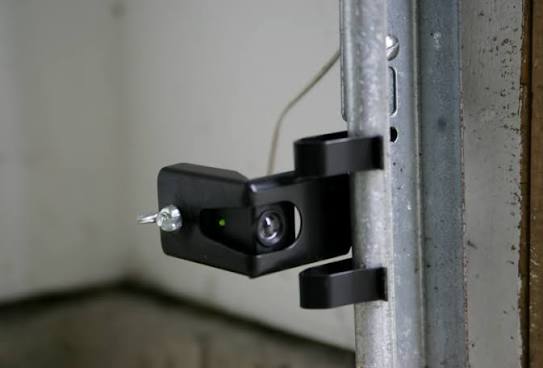
Garage door safety sensors (also called photo eyes or safety reversing sensors) are two small units mounted on each side of your garage door opening. One sends an invisible infrared beam; the other receives it. If anything breaks that beam while the door is closing, the opener instantly reverses.
Here’s why this matters:
- Child safety: Between 1982 and 1990, CPSC documented 46 confirmed deaths of children ages 2–14 from garage door entrapment.
- Pet protection: Sensors mounted at the correct height catch small animals that might wander under a closing door.
- Property protection: Your car, bicycle, or storage items won’t get crushed.
⚠️ Important: Never bypass or disable your safety sensors. Most openers simply won’t operate without them connected.
According to Wikipedia, a garage door opener system can use an electric eye, a door edge sensor, or any device providing equivalent protection by reversing the travel of the closing door.
Tools and Materials You’ll Need
Good news: this is a low-voltage job. No electrician’s license required. Here’s your shopping list:
| Item | Purpose | Approximate Cost |
|---|---|---|
| Phillips-head screwdriver | Terminal screws, brackets | $5–$10 |
| Wire strippers | Strip 7/16″ insulation | $8–$15 |
| Step ladder (6 ft) | Reach motor unit | Already owned |
| 22 AWG 2-conductor bell wire | Sensor-to-opener connection | $10–$20 per 100 ft |
| Electrical tape or wire nuts | Secure splices | $3–$5 |
| Cable staples or clips | Route wires neatly | $5–$8 |
| Flashlight | See terminal labels | Already owned |
| Level (small) | Align sensor brackets | $5–$10 |
Most residential garage door openers use 22-gauge, two-conductor wire for the low-voltage connections between the motor unit, wall button, and sensors.
For runs longer than 50 feet, consider upsizing to 18 AWG to reduce voltage drop.
How To Wire A Garage Door Opener With Sensors: Step-by-Step Guide
This is the core of what you came here for. Follow these steps in order, and you’ll have working sensors in under an hour.
Step 1: Cut the Power (Non-Negotiable)
Unplug the garage door opener from the ceiling outlet, or flip the circuit breaker that powers it.
This isn’t just caution — it protects the opener’s logic board from accidental shorts while you’re working on terminals.
💡 Pro tip: Tape a note on the breaker box so nobody flips it back on while you’re mid-project.
Step 2: Identify Your Sensor Wires
Each sensor has two wires:
- Solid white wire (sometimes plain)
- White wire with a black stripe
Some brands use different color coding (red/black, blue/white), but the principle is identical: one wire is “plain,” one is “striped.” Match like colors together.
Step 3: Mount the Sensors at the Correct Height
This is where most DIYers mess up.
- Measure 4 to 6 inches above the garage floor on each side of the door opening.
- The UL 325 safety standard mandates sensors be mounted no higher than 6 inches (15 cm) above the floor.
- Attach the mounting brackets to the vertical door tracks using the provided bolts or self-tapping screws.
The sending sensor (amber LED) goes on one side; the receiving sensor (green LED) goes on the opposite side. They must face each other directly.
Step 4: Run the Wires to the Opener
Route each sensor’s wire along the wall, up to the ceiling, and over to the motor unit.
Routing best practices:
- Use cable staples every 24 inches to keep wires neat and secure.
- Keep wires away from moving parts — especially the door track and chain/belt.
- Avoid running sensor wire parallel to high-voltage power cables (this causes interference).
- If your garage is pre-wired, wires typically exit near the door tracks and ceiling by the opener.
For a standard single-car garage, you’ll need roughly 25–30 feet of wire per side. For a two-car garage, plan on 35–50 feet per side.
Step 5: Strip and Prepare the Wire Ends
Using your wire strippers, remove exactly 7/16 inch (about 11 mm) of insulation from each wire end.
Don’t nick the copper conductor. If you do, cut and re-strip.
Step 6: Connect Wires at the Opener Terminal Block
Locate the terminal block on the motor head, usually next to the LEARN button.
Here’s the critical wiring connection for most Chamberlain, LiftMaster, and Craftsman openers:
| Wire Color | Terminal | Function |
|---|---|---|
| Two solid white wires (twisted together) | Terminal 2 (white/common) | Sensor power return |
| Two white-with-black-stripe wires (twisted together) | Terminal 3 (gray/safety) | Sensor signal |
How to connect:
- Twist the two solid-white wires from both sensors together.
- Twist the two white-with-black-stripe wires together.
- Insert the twisted white pair into Terminal 2. Tighten the screw firmly.
- Insert the twisted striped pair into Terminal 3. Tighten.
- Give each wire a gentle tug to confirm it’s secure.
📌 Note: For Genie openers, twist striped wires together and attach to Terminal #1; twist plain wires together and attach to Terminal #2.
If your opener uses push-in (quick-connect) terminals instead of screws, use a small flat-head screwdriver to press the release tab, then insert the stripped wire.
Step 7: Insulate Any Splices
If you had to extend wires or make repairs, wrap each splice with electrical tape or use a wire nut.
For low-voltage splices, blue or orange wire nuts work perfectly.
Step 8: Restore Power and Check the LEDs
Plug the opener back in (or flip the breaker). Now look at your sensors:
- Sending sensor: Steady amber/yellow LED = powered and transmitting
- Receiving sensor: Steady green LED = receiving the beam, alignment is good
If either LED is off, blinking, or flickering, move to the troubleshooting section below.
Step 9: Test the Safety Reverse Function
This final test confirms everything works:
- Close the garage door using the wall button.
- While the door is descending, wave a broom handle (or your foot) through the sensor beam.
- The door should immediately stop and reverse upward.
If it does — congratulations! Your sensors are wired correctly. If not, recheck alignment and wiring.
Wiring Diagram (Text Infographic)
242526271234567891011121314151617181920212223
Pre-Wired Garage? Here’s What to Do
Many newer homes come with sensor wires already running behind the drywall. If that’s you:
- Locate the two wires exiting the wall near each door track.
- Identify which is solid and which is striped (use a multimeter continuity test if colors don’t match).
- Connect one color to the solid white wire on the sensor; the other to the white/black striped wire.
- Repeat for both sensors, then connect at the opener as described in Step 6.
💡 If your pre-wired cables use non-standard colors (like Cat5), trace them with a tone generator or label them before connecting.
Common Wiring Mistakes to Avoid
Even experienced DIYers trip over these. Learn from their pain:
| Mistake | Why It’s Bad | The Fix |
|---|---|---|
| Mixing up wire pairs at the opener | Sensors won’t power on or align | Match like colors: white→white, striped→striped |
| Mounting sensors above 6 inches | Won’t detect small children/pets; violates UL 325 | Measure carefully; max 6″ |
| Running wire near power cables | Signal interference causes flickering LEDs | Keep 12″+ separation |
| Over-stripping wire (>7/16″) | Exposed copper can short against adjacent terminals | Strip exactly 7/16″ |
| Leaving splices uninsulated | Moisture causes corrosion and intermittent faults | Tape or wire-nut every splice |
| Ignoring a loose terminal screw | Intermittent connection mimics a bad sensor | Tug-test every connection |
Corroded or damaged wire connections are among the most common causes of garage door sensor issues — pets chewing wires and humidity are frequent culprits.
Troubleshooting: When Your Sensors Won’t Light Up
You followed every step, but something’s off. Here’s how to diagnose:
Neither Sensor Has a Light
- Check that the opener is plugged in and the breaker hasn’t tripped.
- Verify wires are seated in the correct terminals (2 and 3).
- Inspect the entire wire run for cuts, pinches, or chew marks.
One LED Blinks or Flickers
- Loosen the wing nut on the receiving sensor and adjust until the green LED glows steadily.
- Clean both sensor lenses with a soft, dry cloth — dust and spider webs block the beam.
- Check for direct sunlight hitting the receiving sensor (afternoon sun can overwhelm the infrared receiver).
Both LEDs Are On, But Door Still Reverses Randomly
- Ensure nothing is partially blocking the beam (a trash can edge, a hanging cord).
- Confirm sensors are perfectly level and facing each other — even a 2° tilt causes problems.
- Tighten bracket bolts; vibration from the door can shift alignment over time.
Quick Diagnostic Trick
Point the two sensors directly at each other from 12 inches apart, bypassing the installed wiring. If both LEDs light, your sensors are fine — the problem is in your wiring run. Replace the wires between the opener and sensors.
DIY vs. Professional Installation: Cost Comparison
Still on the fence? Here’s the real math:
| Factor | DIY | Professional |
|---|---|---|
| Parts cost (wire + connectors) | $15–$30 | Included |
| Labor cost | $0 (your time: 30–60 min) | $100–$175 for wiring repair |
| Sensor replacement (if needed) | $20–$60 per pair | $125–$300 total |
| Risk of error | Low (low-voltage system) | Minimal |
| Warranty impact | None if done correctly | Covered |
A professional sensor wiring job typically takes about 30 minutes of labor. If you’re comfortable with a screwdriver and can follow instructions, DIY saves you $100+ easily.
Call a pro if:
- Your opener’s logic board appears damaged
- Wires are destroyed inside walls with no access
- The door still malfunctions after correct wiring (possible board failure)
FAQ: How To Wire A Garage Door Opener With Sensors
Q1: Does polarity matter when wiring garage door sensors?
For most major brands (Chamberlain, LiftMaster, Genie), polarity at the opener terminals does not matter as long as both positive wires go to the same terminal and both negative wires go to the other. However, always match like colors to keep things consistent and serviceable. Some older or specialty models may require specific polarity — check your manual.
Q2: What gauge wire should I use for garage door sensors?
Use 22 AWG 2-conductor bell wire — this is the industry standard recommended by LiftMaster, Chamberlain, and Genie. For runs exceeding 50 feet, step up to 18 AWG to prevent voltage drop. The wire should carry a CL2 rating for in-wall use.
Q3: Can I use existing doorbell or thermostat wire for sensors?
Yes. 18 AWG thermostat wire works perfectly, and even 22 AWG security-system wire is acceptable. Just ensure it’s 2-conductor (or use 2 conductors from a 4-conductor cable). Avoid solid-core wire larger than 18 AWG — it won’t fit terminal blocks properly.
Q4: How long do garage door sensors last?
Most sensors last 8 to 15 years, depending on climate, UV exposure, and vibration. They typically survive as long as the opener itself. If your sensors are over 10 years old and showing intermittent issues, replacement ($20–$60 per pair) often makes more sense than repeated repairs.
Q5: My sensors are wired correctly but the door won’t close. What now?
First, confirm both LEDs are solid (amber + green). Then:
- Check for obstructions in the beam path.
- Verify the sensors haven’t shifted (even slightly).
- Unplug the opener for 10 minutes, then restart — this resets the logic board.
- If the problem persists, the sensor pair or logic board may need replacement.
Q6: Can I wire sensors to an opener made by a different brand?
Generally, no. Sensor systems are brand-specific due to differences in voltage, signaling, and connector type. A LiftMaster sensor won’t reliably work with a Genie opener. Always buy sensors matched to your opener brand. Universal kits exist but verify compatibility carefully.
Conclusion
Wiring your garage door opener sensors isn’t rocket science — it’s a straightforward, low-voltage project that saves you $100+ in service calls. The key takeaways:
✅ Mount sensors 4–6 inches above the floor, facing each other
✅ Match wire colors: solid whites to Terminal 2, striped whites to Terminal 3
✅ Strip exactly 7/16 inch of insulation
✅ Secure wires with staples every 24 inches, away from moving parts
✅ Test the auto-reverse before calling the job done
Your sensors are the single most important safety feature on your garage door. Taking 45 minutes to wire them correctly protects your kids, your pets, and your property.
Found this guide helpful? Share it with a friend who’s tackling their own garage project — tag us on social media or pin it for later. A quick share could save someone a costly service call (or worse, an injury). Drop a comment below if you hit a snag — I read every one and love helping troubleshoot.
Now go enjoy that smoothly closing garage door. You earned it. 🔧
Leave a Reply